全志平台GPIO 在sys_config.fex中的具体定义及配置方法
设备树
rk3288 DTS
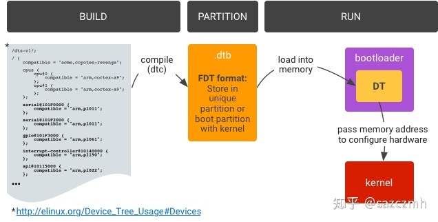
Device Tree 是一种描述硬件的数据结构,它起源于 OpenFirmware(OF)。在 Linux2.6 中,ARM 架构的板机硬件细节过多地被硬编码在 arch/arm/plat-xxx 和 arch/arm/mach-xxx,采用 Device Tree 后,许多硬件的细节可以直接透过它传递给 Linux,而不再需要在 kernel 中进行大量的冗余编码
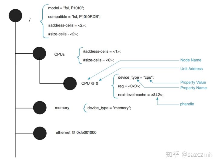
Device Tree 由一系列被命名的结点(node)和属性(property)组成,而结点本身可包含子节点。所谓属性,其实就是成对出现的 name 和 value 。
它基本上就是画一棵电路板上(CPU、总线、设备组成)的树,Bootloader 会将这棵树传递给内核,然后内核可以识别这棵树,并根据它展开出 Linux 内核中的 platform_device、i2c_client、spi_device等设备,而这些设备用到的内存、IRQ 等资源,也被传递给了内核,内核会将这些资源绑定给展开的相应的设备。
| key | value |
|---|---|
| compatible | 用于将设备和驱动绑定起来 |
| model | 描述设备模块信息 |
| status | 设备状态 okey disable |
| reg | 描述设备地址空间资源信息,一般都是某个外设的寄存器地址范围信息 |
./kernel/arch/arm/boot/dts/rk3288-firefly.dts
/dts-v1/;

#include  "rk3288-firefly.dtsi"
#include  "rk3288-wif-f11.dtsi"
#include <dt-bindings/input/input.h>
#include <dt-bindings/pwm/pwm.h>
#include <dt-bindings/display/media-bus-format.h>
/ {
	model = "Firefly-RK3288";
	compatible = "firefly,firefly-rk3288", "rockchip,rk3288";

	chosen {
		bootargs = "earlycon=uart8250,mmio32,0xff690000 swiotlb=1";
	};
	vcc_lcd: vcc-lcd {
		compatible = "regulator-fixed";
		regulator-boot-on;
		enable-active-high;
		pinctrl-names = "default";
		pinctrl-0 = <&lcd_en>;
		regulator-name = "vcc_lcd";
		vin-supply = <&vcc_io>;
	};

        lzt-ec20 {
		compatible = "rockchip,lzt-ec20";
		lte-power-gpios = <&gpio5 17 GPIO_ACTIVE_LOW>;
		led-power-gpios = <&gpio8 8 GPIO_ACTIVE_LOW>;
		status = "okay";
	};

};

&hdmi {
	#address-cells = <1>;
	#size-cells = <0>;
	#sound-dai-cells = <0>;
	status = "disabled";
};

&usb_otg {
	compatible = "rockchip,rk3288_usb20_otg";
	clocks = <&usbphy0>, <&cru HCLK_OTG0>;
	clock-names = "clk_usbphy0", "hclk_usb0";
	resets = <&cru SRST_USBOTG_AHB>,
		 <&cru SRST_USBOTG_PHY>,
		 <&cru SRST_USBOTG_CON>;
	reset-names = "otg_ahb", "otg_phy", "otg_controller";
	/*0 - Normal, 1 - Force Host, 2 - Force Device*/
	rockchip,usb-mode = <0>;
	status = "okay";
};
./kernel/arch/arm/boot/dts/rk3288-firefly.dtsi
#include "rk3288.dtsi"

/ {
	memory {
		device_type = "memory";
		reg = <0x0 0x0 0x0 0x80000000>;
	};

	backlight: backlight {
		compatible = "pwm-backlight";
		brightness-levels = <
			  3   4   5   6   7
			  8   9  10  11  12  13  14  15
			 16  17  18  19  20  21  22  23
			 24  25  26  27  28  29  30  31
			 32  33  34  35  36  37  38  39
			 40  41  42  43  44  45  46  47
			 48  49  50  51  52  53  54  55
			 56  57  58  59  60  61  62  63
			 64  65  66  67  68  69  70  71
			 72  73  74  75  76  77  78  79
			 80  81  82  83  84  85  86  87
			 88  89  90  91  92  93  94  95
			 96  97  98  99 100 101 102 103
			104 105 106 107 108 109 110 111
			112 113 114 115 116 117 118 119
			120 121 122 123 124 125 126 127
			128 129 130 131 132 133 134 135
			136 137 138 139 140 141 142 143
			144 145 146 147 148 149 150 151
			152 153 154 155 156 157 158 159
			160 161 162 163 164 165 166 167
			168 169 170 171 172 173 174 175
			176 177 178 179 180 181 182 183
			184 185 186 187 188 189 190 191
			192 193 194 195 196 197 198 199
			200 201 202 203 204 205 206 207
			208 209 210 211 212 213 214 215
			216 217 218 219 220 221 222 223
			224 225 226 227 228 229 230 231
			232 233 234 235 236 237 238 239
			240 241 242 243 244 245 246 247
			248 249 250 251 252 253 254 255>;
		default-brightness-level = <255>;
		pwms = <&pwm0 0 25000 0>;
		pwm-names = "backlight";
		power-supply = <&vcc_sys>;
	};

	sound {
		compatible = "simple-audio-card";
		simple-audio-card,name = "SPDIF";
		simple-audio-card,dai-link@1 {
			cpu { sound-dai = <&spdif>; };
			codec { sound-dai = <&spdif_out>; };
		};
	};

	vcc_otg_5v: usb-otg-regulator {
		compatible = "regulator-fixed";
		enable-active-high;
		gpio = <&gpio0 12 GPIO_ACTIVE_HIGH>;
		pinctrl-names = "default";
		pinctrl-0 = <&otg_vbus_drv>;
		regulator-name = "vcc_otg_5v";
		regulator-min-microvolt = <5000000>;
		regulator-max-microvolt = <5000000>;
		regulator-always-on;
		vin-supply = <&vcc_5v>;
	};

	wireless-wlan {
		compatible = "wlan-platdata";
		rockchip,grf = <&grf>;
		wifi_chip_type = "ap6335";
		sdio_vref = <1800>;
		WIFI,host_wake_irq = <&gpio4 30 GPIO_ACTIVE_HIGH>;
		status = "okay";
	};

}


&emmc {
	bus-width = <8>;
	cap-mmc-highspeed;
	disable-wp;
	non-removable;
	num-slots = <1>;
	pinctrl-names = "default";
	pinctrl-0 = <&emmc_clk>, <&emmc_cmd>, <&emmc_pwr>, <&emmc_bus8>;
	vmmc-supply = <&vcc_io>;
	vqmmc-supply = <&vcc_flash>;
	status = "okay";
};
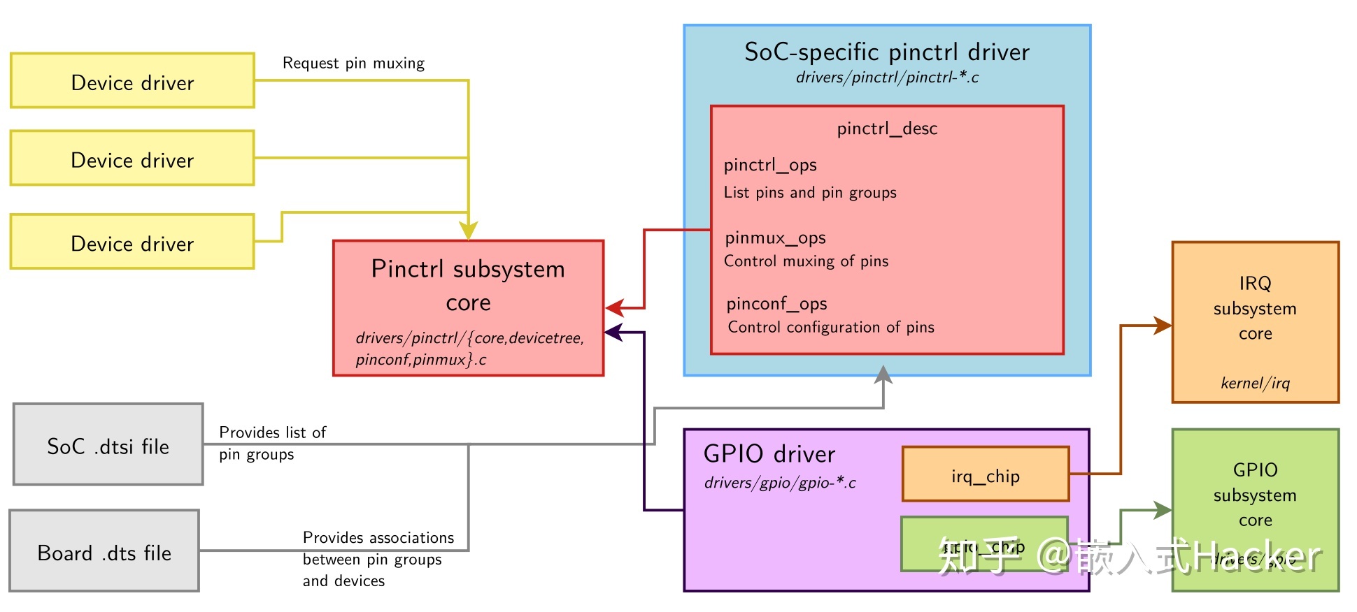
pinctrl
众所周知,ARM SoC提供了十分丰富的硬件接口,而接口物理上的表现就是一个个的pin(或者叫做pad, finger等)。为了实现丰富的硬件功能,SoC的pin需要实现复用功能,即单独的pin需要提供不同功能,例如,pin0既可以作为GPIO,可以也用于i2c的SCL,通过pin相关的复用寄存器来切换不同的功能。除此之外,软件还可以通过寄存器配置pin相关的电气特性,例如,上拉/下拉、驱动能力、开漏等。
GPIO
GPIO, 全称 General-Purpose Input/Output(通用输入输出),是一种软件运行期间能够动态配置和控制的通用引脚, 功能如下:
- 输出设定电平:可以根据用户的需要,向驱动写入相应的值(比如1或0)然后GPIO输出高低电平(高=1;低=0);
- 读取输入电平:可以读取GPIO上输入的高低电平;实际的应用比如按键或者其他一些传感器的信号;
- 触发外部中断:输入信号可以作为中断信号,包括边沿触发,高电平触发,低电平触发等等;
架构
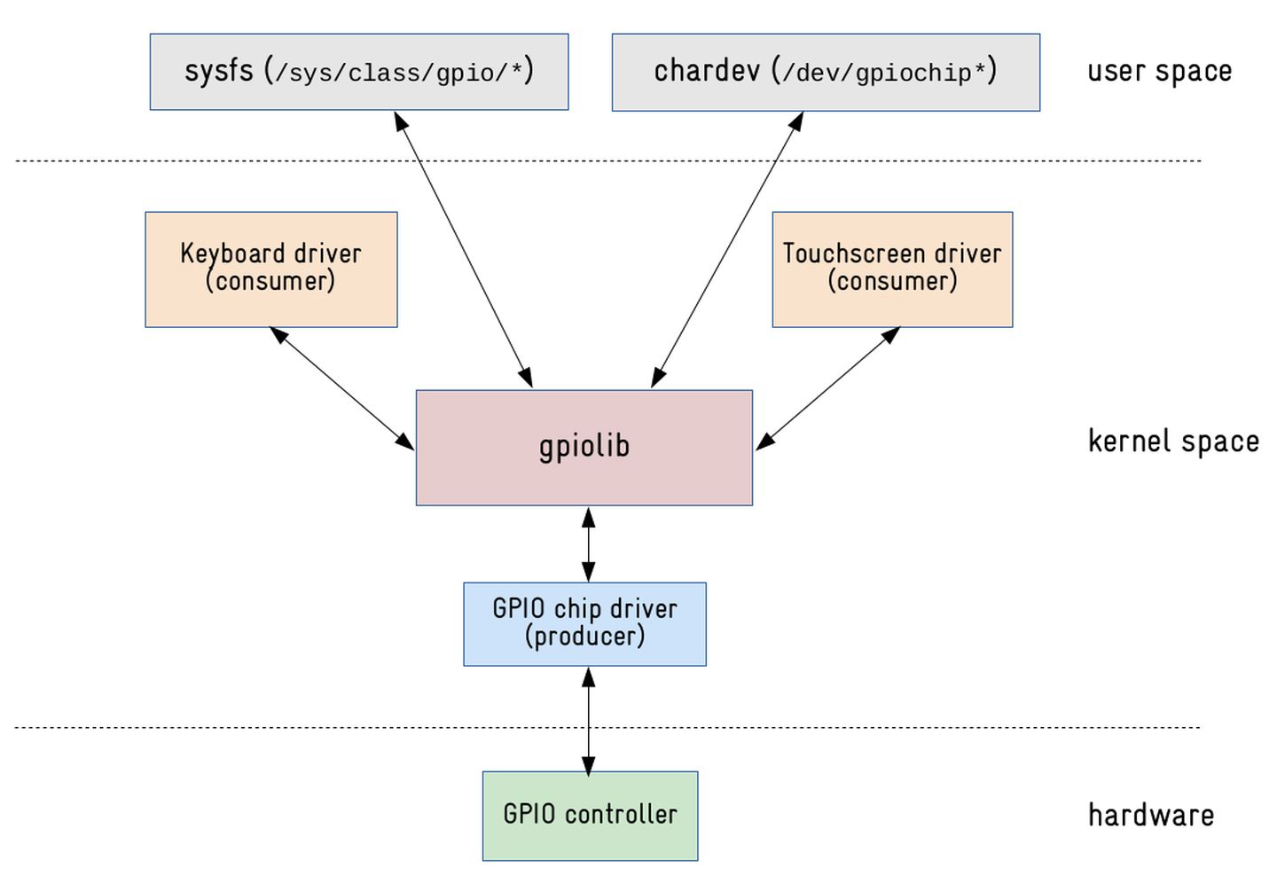
正常情况下,驱动工程师不需要了解 gpio chip driver 和 gpiolib:
- 驱动工程师负责编写 gpio consumer drvier;
- 芯片厂商的 bsp 工程师负责编写 gpio chip driver;
- 开源社区里的大牛负责 gpiolib 的核心实现;
RK3288 GPIO
RK3288 有 9 组 GPIO bank: GPIO0,GPIO1, …, GPIO8。每组又以 A0~A7, B0~B7, C0~C7, D0~D7 作为编号区分(不是所有 bank 都有全部编号,例如 GPIO5 就只有 B0~B7, C0~C3)。
dts 配置解释
GPIO4_C5 = <&gpio4 21 GPIO_ACTIVE_LOW>
21 = 16(C组) + 5
A5 = 0 + 5 = 5 B5 = 8 + 5 = 13 C5 = 16 + 5 = 21 D5 = 24 + 5 = 29
rk3288:/sys/class/gpio # ls
export gpiochip0 gpiochip120 gpiochip152 gpiochip184 gpiochip216 gpiochip24 gpiochip248 gpiochip56 gpiochip88 unexport

rk3288:/sys/class/gpio/gpiochip0 # ls -al
drwxr-xr-x  3 root root    0 2021-12-24 13:56 .
drwxr-xr-x 11 root root    0 2021-12-24 13:56 ..
-r--r--r--  1 root root 4096 2021-12-24 13:59 base
lrwxrwxrwx  1 root root    0 2021-12-24 13:59 device -> ../../../pinctrl
-r--r--r--  1 root root 4096 2021-12-24 13:59 label
-r--r--r--  1 root root 4096 2021-12-24 13:59 ngpio
drwxr-xr-x  2 root root    0 2021-12-24 13:56 power
lrwxrwxrwx  1 root root    0 2021-12-24 13:59 subsystem -> ../../../../../class/gpio
-rw-r--r--  1 root root 4096 2021-12-24 13:56 uevent

rk3288:/sys/class/gpio/gpiochip0 # ls -al power/
drwxr-xr-x 2 root root    0 2021-12-24 13:56 .
drwxr-xr-x 3 root root    0 2021-12-24 13:56 ..
-rw-r--r-- 1 root root 4096 2021-12-24 14:02 async
-rw-r--r-- 1 root root 4096 2021-12-24 14:02 autosuspend_delay_ms
-rw-r--r-- 1 root root 4096 2021-12-24 14:02 control
-r--r--r-- 1 root root 4096 2021-12-24 14:02 runtime_active_kids
-r--r--r-- 1 root root 4096 2021-12-24 14:02 runtime_active_time
-r--r--r-- 1 root root 4096 2021-12-24 14:02 runtime_enabled
-r--r--r-- 1 root root 4096 2021-12-24 14:02 runtime_status
-r--r--r-- 1 root root 4096 2021-12-24 14:02 runtime_suspended_time
-r--r--r-- 1 root root 4096 2021-12-24 14:02 runtime_usage
查看GPIO状态
cat sys/kernel/debug/gpio
adb root
adb remount

rk3288:/ # cd data/
rk3288:/data #
rk3288:/data #
rk3288:/data # mkdir debugfs
rk3288:/data # mount -t debugfs debug debugfs
rk3288:/data # cat debugfs/gpio
GPIOs 0-23, platform/pinctrl, gpio0:
 gpio-5   (                    |power               ) in  hi
 gpio-6   (                    |vcc_phy             ) out hi
 gpio-11  (                    |vcc28_dvp           ) out hi
 gpio-12  (                    |otg_drv_gpio        ) out lo
 gpio-13  (                    |enable              ) in  lo
 gpio-14  (                    |vcc_host_5v         ) out hi

GPIOs 24-55, platform/pinctrl, gpio1:

GPIOs 56-87, platform/pinctrl, gpio2:

GPIOs 88-119, platform/pinctrl, gpio3:

GPIOs 120-151, platform/pinctrl, gpio4:
 gpio-128 (                    |mdio-reset          ) out hi
 gpio-139 (                    |bt_default_rts      ) in  hi
 gpio-146 (                    |bt_default_wake     ) in  hi
 gpio-148 (                    |reset               ) out hi
 gpio-149 (                    |bt_default_reset    ) out lo
 gpio-151 (                    |bt_default_wake_host) in  hi

GPIOs 152-183, platform/pinctrl, gpio5:
 gpio-169 (                    |?                   ) out hi
 gpio-171 (                    |?                   ) out lo

GPIOs 184-215, platform/pinctrl, gpio6:

GPIOs 216-247, platform/pinctrl, gpio7:
 gpio-218 (                    |enable              ) out hi
 gpio-227 (                    |vcc_sd              ) out hi

GPIOs 248-263, platform/pinctrl, gpio8:
 gpio-249 (                    |?                   ) out hi
 gpio-250 (                    |?                   ) out lo
 gpio-256 (                    |?                   ) out lo
GPIO-电源键
DTS
&pinctrl {

	rk_key: rockchip-key {
		compatible = "rockchip,key";
		status = "okay";

		io-channels = <&saradc 1>;
		power-key {
			gpios = <&gpio0 5 GPIO_ACTIVE_LOW>;
			linux,code = <116>;
			pinctrl-names = "default";
			pinctrl-0 = <&pwrbtn>;
			label = "power";
			gpio-key,wakeup;
		};
        }

	buttons {
		pwrbtn: pwrbtn {
			rockchip,pins = <0 5 RK_FUNC_GPIO &pcfg_pull_up>;
		};
	};

}
kernel/drivers/input/keyboard/gpio_keys.c
enum rk_key_type {
	TYPE_GPIO = 1,
	TYPE_ADC
};

struct rk_keys_button {
	struct device *dev;
	u32 type;		/* TYPE_GPIO, TYPE_ADC */
	u32 code;		/* key code */
	const char *desc;	/* key label */
	u32 state;		/* key up & down state */
	int gpio;		/* gpio only */
	int adc_value;		/* adc only */
	int adc_state;		/* adc only */
	int active_low;		/* gpio only */
	int wakeup;		/* gpio only */
	struct timer_list timer;
};

static const struct of_device_id rk_key_match[] = {
	{ .compatible = "rockchip,key", .data = NULL},
	{},
};
MODULE_DEVICE_TABLE(of, rk_key_match);

void rk_send_power_key(int state)
{
	if (!sinput_dev)
		return;
	if (state) {
		input_report_key(sinput_dev, KEY_POWER, 1);
		input_sync(sinput_dev);
	} else {
		input_report_key(sinput_dev, KEY_POWER, 0);
		input_sync(sinput_dev);
	}
}
EXPORT_SYMBOL(rk_send_power_key);
kernel/include/linux/input.h
void input_event(struct input_dev *dev, unsigned int type, unsigned int code, int value);

static inline void input_report_key(struct input_dev *dev, unsigned int code, int value)
{
	input_event(dev, EV_KEY, code, !!value);
}
kernel/drivers/input/input.c
void input_event(struct input_dev *dev,
		 unsigned int type, unsigned int code, int value)
{
	unsigned long flags;

	if (is_event_supported(type, dev->evbit, EV_MAX)) {

		spin_lock_irqsave(&dev->event_lock, flags);
		input_handle_event(dev, type, code, value);
		spin_unlock_irqrestore(&dev->event_lock, flags);
	}
}
EXPORT_SYMBOL(input_event);
gpio sys
应用层通过sys节点控制风扇开关
- 查看GPIO编号 /sys/kernel/debug/gpio
- 注释掉dts中的GPIO控制: //vcc_fan = <&r_pio PL 10 1 0xffffffff 0xffffffff 0>;
- CONFIG_GPIO_SYSFS=y
- init.rc 中增加权限
    chmod 777 /sys/class/gpio/export
    chmod 777 /sys/class/gpio/gpio362/direction
    write /sys/class/gpio/export 362
    write /sys/class/gpio/gpio362/direction out
    chmod 777 /sys/class/gpio/gpio362/value
- 控制 /sys/class/gpio/gpio362/value 节点的值(1 or 0)进行控制
全志 GPIO
sys/kernel/debug/sunxi_pinctrl/

data                    // 引脚的电平状态
dlevel                  // 引脚的驱动等级(结合芯片手册)
function                // 引脚的功能配置(结合芯片手册, 输入\输出\功能复用)
platform                // 当前平台
pull                    // 上下拉功能配置
sunxi_pin               // 指定引脚
sunxi_pin_configure     // 引脚所有的配置信息
如果通过命令控制GPIO
- 设定指定引脚
root@sun8i:/proc/sys/debug/sunxi_pinctrl# echo PE24 > sunxi_pin
echo PE24 > sunxi_pin
- 查看引脚配置(注意 data 的值)
root@sun8i:/proc/sys/debug/sunxi_pinctrl# cat sunxi_pin_configure
cat sunxi_pin_configure
printf register value...
pin[PE24] function:  1;                 register addr: 0xf1c2089c
pin[PE24] data:  1(default value : 0);  register addr: 0xf1c208a0
pin[PE24] dleve: 1(default value : 1);  register addr: 0xf1c208a8
pin[PE24] pull:  0(default value : 0);  register addr: 0xf1c208b0
- 设置输出低电平(此时可以拿万用表或者示波器测量该引脚的实际状态)
root@sun8i:/proc/sys/debug/sunxi_pinctrl# echo PE24 0 > data
echo PE24 0 > data
- 查看引脚配置信息(注意 data 的值)
root@sun8i:/proc/sys/debug/sunxi_pinctrl# cat sunxi_pin_configure
cat sunxi_pin_configure
printf register value...
pin[PE24] function:  1;                 register addr: 0xf1c2089c
pin[PE24] data:  0(default value : 0);  register addr: 0xf1c208a0
pin[PE24] dleve: 1(default value : 1);  register addr: 0xf1c208a8
pin[PE24] pull:  0(default value : 0);  register addr: 0xf1c208b0
- 设置输出高电平(此时可以拿万用表或者示波器测量该引脚的实际状态)
root@sun8i:/proc/sys/debug/sunxi_pinctrl# echo PE24 1 > data
echo PE24 1 > data
- 查看引脚配置信息(注意 data 的值)
root@sun8i:/proc/sys/debug/sunxi_pinctrl# cat sunxi_pin_configure
cat sunxi_pin_configure
printf register value...
pin[PE24] function:  1;                 register addr: 0xf1c2089c
pin[PE24] data:  1(default value : 0);  register addr: 0xf1c208a0
pin[PE24] dleve: 1(default value : 1);  register addr: 0xf1c208a8
pin[PE24] pull:  0(default value : 0);  register addr: 0xf1c208b0
全志GPIO配置
sys_config.fex
port:PC 15 <3> <1> <3>
Port:端口+组内序号<功能分配><内部电阻><驱动能力><输出电平>
- 端口编号: 例如:PA,PB,PC, …
- 组内序号: 例如:0,1, 2, …
- 功能选择: 指定PIN 的功能,具体参考IC datasheet(输入、输出)
- 内部电阻: 包括三种状态,0:上下拉禁用(默认), 1:上拉,2:下拉
- 驱动能力,柯配置驱动能力四级别,0(默认),1, 2, 3
- 输出电平,0或1,只有当PIN配成 输出是才有效
dts
cd-gpios = <&pio PF 6 6 1 3 0xffffffff>;
GPIO 计算
./kernel/linux-4.9/include/linux/sunxi-gpio.h
/* pin group base number name space,
 * the max pin number : 26*32=832.
 */
#define SUNXI_BANK_SIZE 32

#define SUNXI_PA_BASE	0

#define SUNXI_PB_BASE	32

#define SUNXI_PC_BASE	64

#define SUNXI_PD_BASE	96

#define SUNXI_PE_BASE	128

#define SUNXI_PF_BASE	160

#define SUNXI_PG_BASE	192

#define SUNXI_PH_BASE	224

#define SUNXI_PI_BASE	256

#define SUNXI_PJ_BASE	288

#define SUNXI_PK_BASE	320

#define SUNXI_PL_BASE	352

#define SUNXI_PM_BASE	384

#define SUNXI_PN_BASE	416

#define SUNXI_PO_BASE	448

#define AXP_PIN_BASE	1024
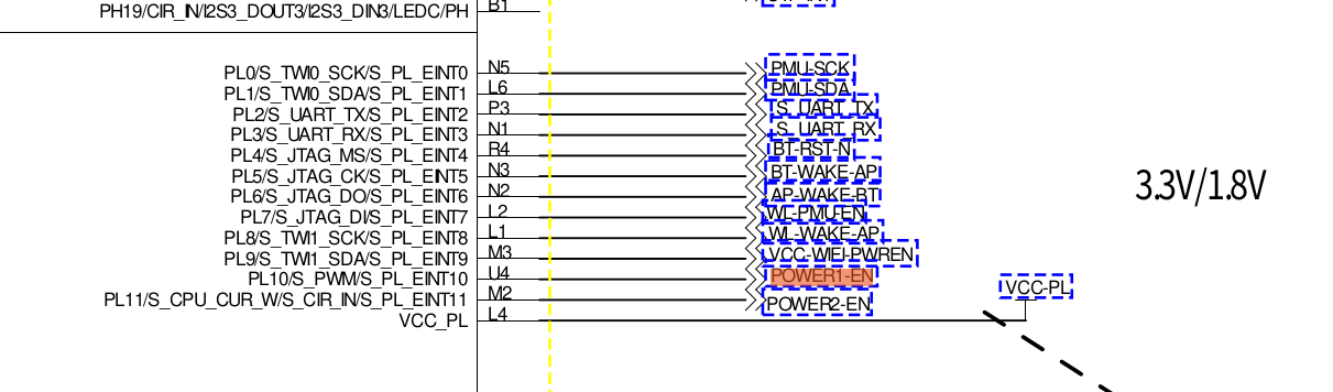
vcc_fan = <&r_pio PL 10 1 0xffffffff 0xffffffff 0>;
fan_gpio = (SUNXI_PL_BASE)352 + 10 = 362