Firefly-RK3399
RK3399 支持五路 UART:UART0, UART1, UART2, UART3, UART4,都拥有两个 64 字节的 FIFO 缓冲区,用于数据接收和发送。 其中:
- UART0 用于蓝牙传输,UART2 用作调试串口,只有 UART0 和 UART3 支持硬件自动流控。
- 支持比特率 115.2Kbps,460.8Kbps,921.6Kbps,1.5Mbps,3Mbps,4Mbps。
- 支持自选波特率,即使使用非整数时钟分频器
- 支持基于中断或基于 DMA 的模式
- 支持 5-8l 位宽度传输
驱动代码
kernel/drivers/tty/serial/8250$ tree
.
├── 8250_accent.c
├── 8250_acorn.c
├── 8250_boca.c
├── 8250_core.c
├── 8250_dma.c
├── 8250_dw.c
├── 8250_early.c
├── 8250_em.c
├── 8250_exar_st16c554.c
├── 8250_fintek.c
├── 8250_fourport.c
├── 8250_fsl.c
├── 8250_gsc.c
├── 8250.h
├── 8250_hp300.c
├── 8250_hub6.c
├── 8250_ingenic.c
├── 8250_lpc18xx.c
├── 8250_mid.c
├── 8250_mtk.c
├── 8250_omap.c
├── 8250_pci.c
├── 8250_pnp.c
├── 8250_port.c
├── 8250_uniphier.c
├── Kconfig
├── Makefile
└── serial_cs.c
串口设备
ls -al dev/tty*
crw-rw-rw- 1 root      root           5,   0 2013-01-18 16:50 dev/tty
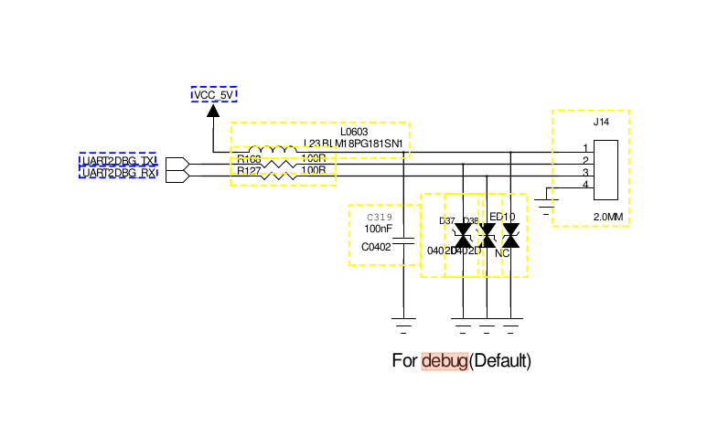
crw------- 1 root      root         254,   0 2013-01-18 16:50 dev/ttyFIQ0                   // debug uart2_c
crw-rw---- 1 bluetooth net_bt_stack   4,  64 2013-01-18 16:50 dev/ttyS0                     // uart0
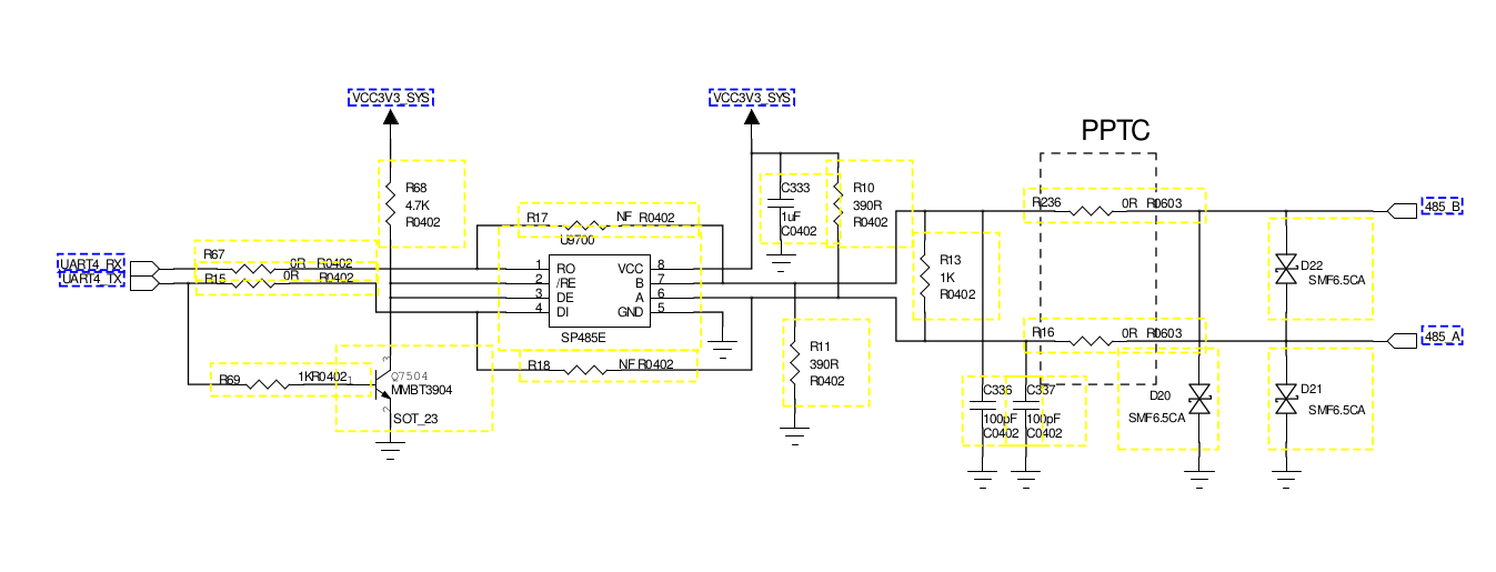
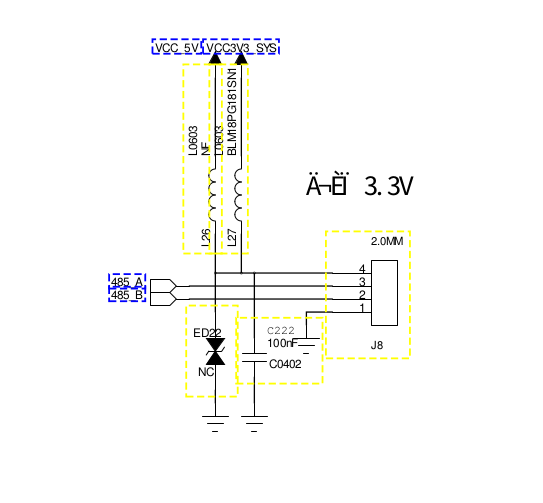
lrwxrwxrwx 1 root      root               10 2013-01-18 16:50 dev/ttyS3 -> /dev/ttyS4       // RS485 uart4
crwxrwxrwx 1 root      root           4,  68 2013-01-18 16:50 dev/ttyS4
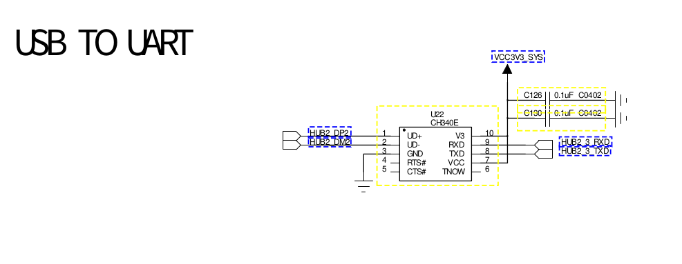
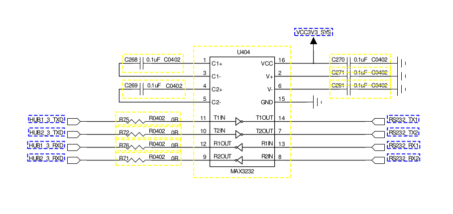
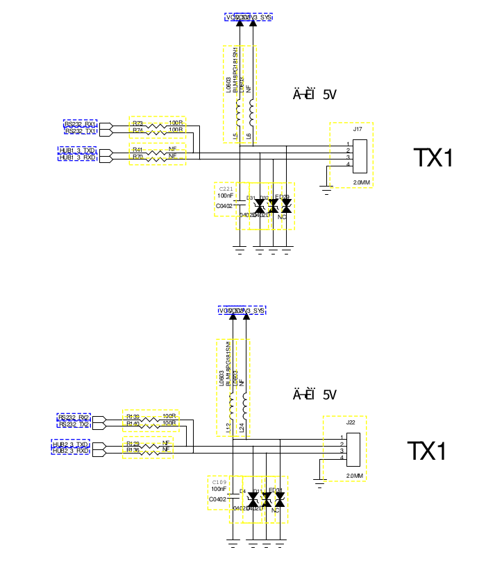
crw-rw-rw- 1 radio     radio        188,   0 2013-01-18 16:50 dev/ttyUSB0                   // RS232
crw-rw-rw- 1 radio     radio        188,   1 2013-01-18 16:50 dev/ttyUSB1                   // RS232
原理图
RS485
RS232
UART DEBUG
DTS 配置
./arch/arm64/boot/dts/rockchip/rk3399.dtsi
        aliases {
                i2c0 = &i2c0;
                i2c1 = &i2c1;
                i2c2 = &i2c2;
                i2c3 = &i2c3;
                i2c4 = &i2c4;
                i2c5 = &i2c5;
                i2c6 = &i2c6;
                i2c7 = &i2c7;
                i2c8 = &i2c8;
                serial0 = &uart0;
                serial1 = &uart1;
                serial2 = &uart2;
                serial3 = &uart3;
                serial4 = &uart4;
                dsi0 = &dsi;
                dsi1 = &dsi1;
        };


	uart0: serial@ff180000 {
		compatible = "rockchip,rk3399-uart", "snps,dw-apb-uart";
		reg = <0x0 0xff180000 0x0 0x100>;
		clocks = <&cru SCLK_UART0>, <&cru PCLK_UART0>;
		clock-names = "baudclk", "apb_pclk";
		interrupts = <GIC_SPI 99 IRQ_TYPE_LEVEL_HIGH 0>;
		reg-shift = <2>;
		reg-io-width = <4>;
		pinctrl-names = "default";
		pinctrl-0 = <&uart0_xfer &uart0_cts &uart0_rts>;
		status = "disabled";
	};

	uart1: serial@ff190000 {
		compatible = "rockchip,rk3399-uart", "snps,dw-apb-uart";
		reg = <0x0 0xff190000 0x0 0x100>;
		clocks = <&cru SCLK_UART1>, <&cru PCLK_UART1>;
		clock-names = "baudclk", "apb_pclk";
		interrupts = <GIC_SPI 98 IRQ_TYPE_LEVEL_HIGH 0>;
		reg-shift = <2>;
		reg-io-width = <4>;
		pinctrl-names = "default";
		pinctrl-0 = <&uart1_xfer>;
		status = "disabled";
	};

	uart2: serial@ff1a0000 {
		compatible = "rockchip,rk3399-uart", "snps,dw-apb-uart";
		reg = <0x0 0xff1a0000 0x0 0x100>;
		clocks = <&cru SCLK_UART2>, <&cru PCLK_UART2>;
		clock-names = "baudclk", "apb_pclk";
		interrupts = <GIC_SPI 100 IRQ_TYPE_LEVEL_HIGH 0>;
		reg-shift = <2>;
		reg-io-width = <4>;
		pinctrl-names = "default";
		pinctrl-0 = <&uart2c_xfer>;
		status = "disabled";
	};

	uart3: serial@ff1b0000 {
		compatible = "rockchip,rk3399-uart", "snps,dw-apb-uart";
		reg = <0x0 0xff1b0000 0x0 0x100>;
		clocks = <&cru SCLK_UART3>, <&cru PCLK_UART3>;
		clock-names = "baudclk", "apb_pclk";
		interrupts = <GIC_SPI 101 IRQ_TYPE_LEVEL_HIGH 0>;
		reg-shift = <2>;
		reg-io-width = <4>;
		pinctrl-names = "default";
		pinctrl-0 = <&uart3_xfer &uart3_cts &uart3_rts>;
		status = "disabled";
	};

        uart4: serial@ff370000 {
                compatible = "rockchip,rk3399-uart", "snps,dw-apb-uart";
                reg = <0x0 0xff370000 0x0 0x100>;
                clocks = <&pmucru SCLK_UART4_PMU>, <&pmucru PCLK_UART4_PMU>;
                clock-names = "baudclk", "apb_pclk";
                interrupts = <GIC_SPI 102 IRQ_TYPE_LEVEL_HIGH 0>;
                reg-shift = <2>;
                reg-io-width = <4>;
                pinctrl-names = "default";
                pinctrl-0 = <&uart4_xfer>;
                status = "disabled";
        };


	pinctrl: pinctrl {
		compatible = "rockchip,rk3399-pinctrl";
		rockchip,grf = <&grf>;
		rockchip,pmu = <&pmugrf>;
		#address-cells = <0x2>;
		#size-cells = <0x2>;
		ranges;

		uart0 {
			uart0_xfer: uart0-xfer {
				rockchip,pins =
					<2 16 RK_FUNC_1 &pcfg_pull_up>,
					<2 17 RK_FUNC_1 &pcfg_pull_none>;
			};

			uart0_cts: uart0-cts {
				rockchip,pins =
					<2 18 RK_FUNC_1 &pcfg_pull_none>;
			};

			uart0_rts: uart0-rts {
				rockchip,pins =
					<2 19 RK_FUNC_1 &pcfg_pull_none>;
			};
		};

		uart1 {
			uart1_xfer: uart1-xfer {
				rockchip,pins =
					<3 12 RK_FUNC_2 &pcfg_pull_up>,
					<3 13 RK_FUNC_2 &pcfg_pull_none>;
			};
		};

		uart2a {
			uart2a_xfer: uart2a-xfer {
				rockchip,pins =
					<4 8 RK_FUNC_2 &pcfg_pull_up>,
					<4 9 RK_FUNC_2 &pcfg_pull_none>;
			};
		};

		uart2b {
			uart2b_xfer: uart2b-xfer {
				rockchip,pins =
					<4 16 RK_FUNC_2 &pcfg_pull_up>,
					<4 17 RK_FUNC_2 &pcfg_pull_none>;
			};
		};

		uart2c {
			uart2c_xfer: uart2c-xfer {
				rockchip,pins =
					<4 19 RK_FUNC_1 &pcfg_pull_up>,
					<4 20 RK_FUNC_1 &pcfg_pull_none>;
			};
		};

		uart3 {
			uart3_xfer: uart3-xfer {
				rockchip,pins =
					<3 14 RK_FUNC_2 &pcfg_pull_up>,
					<3 15 RK_FUNC_2 &pcfg_pull_none>;
			};

			uart3_cts: uart3-cts {
				rockchip,pins =
					<3 16 RK_FUNC_2 &pcfg_pull_none>;
			};

			uart3_rts: uart3-rts {
				rockchip,pins =
					<3 17 RK_FUNC_2 &pcfg_pull_none>;
			};
		};

		uart4 {
			uart4_xfer: uart4-xfer {
				rockchip,pins =
					<1 7 RK_FUNC_1 &pcfg_pull_up>,
					<1 8 RK_FUNC_1 &pcfg_pull_none>;
			};
		};

        }
使能 rk3399-evb.dtsi
        wireless-bluetooth {
                uart0_gpios: uart0-gpios {
                        rockchip,pins = <2 19 RK_FUNC_GPIO &pcfg_pull_none>;
                };
        };

        wireless-bluetooth {
                compatible = "bluetooth-platdata";
                clocks = <&rk808 1>;
                clock-names = "ext_clock";
                //wifi-bt-power-toggle;
                uart_rts_gpios = <&gpio2 19 GPIO_ACTIVE_LOW>; /* GPIO2_C3 */
                pinctrl-names = "default", "rts_gpio";
                pinctrl-0 = <&uart0_rts>;
                pinctrl-1 = <&uart0_gpios>;
                //BT,power_gpio  = <&gpio3 19 GPIO_ACTIVE_HIGH>; /* GPIOx_xx */
                BT,reset_gpio    = <&gpio0 9 GPIO_ACTIVE_HIGH>; /* GPIO0_B1 */
                BT,wake_gpio     = <&gpio2 27 GPIO_ACTIVE_HIGH>; /* GPIO2_D3 BT_WAKE */
                BT,wake_host_irq = <&gpio0 4 GPIO_ACTIVE_HIGH>; /* GPIO0_A4 */
                status = "okay";
        };

&uart0 {
        pinctrl-names = "default";
        pinctrl-0 = <&uart0_xfer &uart0_cts>;
        status = "okay";
};

&uart2 {
        status = "okay";
};

&uart4{
        status = "okay";
};
串口调试 rk3399-android.dtsi
该节点驱动加载后会注册/dev/ttyFIQ0 设备,需要注意的是 rockchip,serial-id 即便改了,注册的也是ttyFIQ0。
        chosen {
                bootargs = "earlycon=uart8250,mmio32,0xff1a0000 swiotlb=1 coherent_pool=1m";  /*0xff1a0000 是 uart2 的物理基地址,不同的串口基地址不一样*/
        };

        fiq_debugger: fiq-debugger {
                compatible = "rockchip,fiq-debugger";
                rockchip,serial-id = <2>;        /* 设置串口id,如果想换不同的串口就改这个ID*/
                rockchip,wake-irq = <0>;
                rockchip,irq-mode-enable = <0>;  /* If enable uart uses irq instead of fiq */
                rockchip,baudrate = <1500000>;  /* Only 115200 and 1500000 */
                pinctrl-names = "default";
                pinctrl-0 = <&uart2c_xfer>;  /*换了不同的串口后,需要配置iomux*/
                interrupts = <GIC_SPI 150 IRQ_TYPE_LEVEL_HIGH 0>;
        };

&uart2 {
        status = "disabled";
};
启动日志
[    0.000000] bootconsole [uart0] enabled
[    0.000000] Kernel command line: earlycon=uart8250,mmio32,0xff1a0000 swiotlb=1 coherent_pool=1m console=ttyFIQ0 androidboot.baseband=N/A androidboot.selinux=permissive androidboot.hardware=rk30board androidboot.console=ttyFIQ0 init=/init mtdparts=rk29xxnand:0x00002000@0x00002000(uboot),0x00002000@0x00004000(trust),0x00002000@0x00006000(misc),0x00008000@0x00008000(resource),0x0000C000@0x00010000(kernel),0x00010000@0x0001C000(boot),0x00020000@0x0002C000(recovery),0x00038000@0x0004C000(backup),0x00040000@0x00084000(cache),0x00300000@0x000C4000(system),0x00008000@0x003C4000(metadata),0x00000040@0x003CC000(verity_mode),0x00002000@0x003CC040(reserved),0x00000400@0x003CE040(frp),0x00004000@0x004EE000(oem),-@0x003CE440(userdata) storagemedia=emmc androidboot.oem_unlocked=0 uboot_logo=0x02000000@0x7dc00000 loader.timestamp=2022-09-14_14:31:14 SecureBootCheckOk=0
[    0.177845] fiq debugger fiq mode enabled
[    0.178491] console [ttyFIQ0] enabled
[    0.179184] bootconsole [uart0] disabled
[    0.179752] Registered fiq debugger ttyFIQ0
[    0.389369] ff180000.serial: ttyS0 at MMIO 0xff180000 (irq = 36, base_baud = 1500000) is a 16550A
[    0.389831] ff370000.serial: ttyS4 at MMIO 0xff370000 (irq = 38, base_baud = 1500000) is a 16550A
[    2.668311] usbserial: USB Serial support registered for ch341-uart
[    3.419270] ch341 1-1.2:1.0: ch341-uart converter detected
[    3.421184] usb 1-1.2: ch341-uart converter now attached to ttyUSB0
[    3.432463] ch341 2-1.2:1.0: ch341-uart converter detected
[    3.434389] usb 2-1.2: ch341-uart converter now attached to ttyUSB1
0
次点赞