Rockchip_Developer_Guide_DRM_Panel_Porting_CN.pdf
Rockchip_Developer_Guide_DRM_Display_Driver_CN.pdf
显示系统的硬件框架
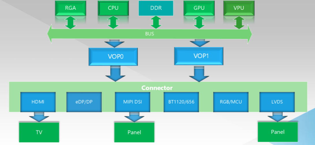
VOP 1.0 显示子系统架构
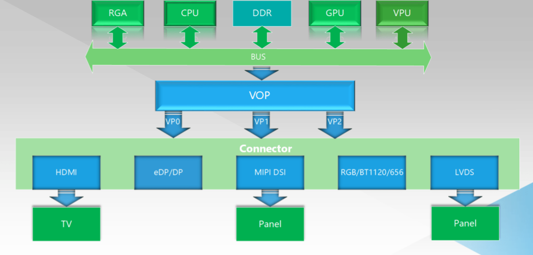
VOP 2.0 显示子系统架构
从上面的 DSS 框图可以看到,在整个显示通路的最后端,是由 RGA,GPU、VPU 组成的显示图形加速模块,他们是专门针对图像处理优化设计的硬件 IP,能够高效的进行图像的生成和进一步处理(比如 GPU 通过 opengl 功能提供图像渲染功能,RGA 可以对图像数据进行缩放,旋转,合成等 2D 处理,VPU 可以高效的进行视频解码),从而减轻 CPU负担。
经过这些图像加速模块处理后的数据会存放在 DDR 中,然后由 VOP 读取,根据应用需求进行 Alpha 叠加,颜色空间转换,gamma 矫正,HDR 转换 等处理后,再发送到对应的显示接口模块(HDMI/DP/DSI/RGB/LVDS), 这些接口模块会把接收到的数据转换成符合各自协议的数据流,发送到显示器或者屏幕上,呈现在最终用户眼前。
目前 Rockchip 平台上存在两种 VOP 架构—— VOP 1.0 和 VOP 2.0,他们的主要的区别是对多显的支持方式不同,VOP 1.0 是用多 VOP 的方式来实现多屏幕显示,即正常情况下,一个 VOP 在同一时刻只能输出一路独立的显示时序,驱动一个屏幕显示独立的内容。如果需要实现双屏显示,则需要有两个 VOP 来实现,所以在 RK3288,RK3399,RK3326/PX30 的支持双显的平台上,都有两个独立的 VOP。
VOP 2.0 采用了统一显示架构,即整个 SOC 上只存在一个 VOP,但是在 VOP 的后端设计了多路独立的 Video Port(简称 VP) 输出接口,这些 VP 能够同时独立工作,并且输出相关独立的显示时序。比如在上面的 VOP 2.0 框图中,有三个VP,就能同时实现三屏异显。
调试方法
adb shell cat /d/dri/0/summary 查看 VOP 状态
VOP [ff930000.vop]: ACTIVE
    Connector: LVDS
	overlay_mode[0] bus_format[100a] output_mode[0] color_space[0]
    Display mode: 1920x1080p60
	clk[148500] real_clk[148500] type[8] flag[a]
	H: 1920 2140 2170 2200
	V: 1080 1105 1115 1125
    win0-0: ACTIVE
	format: AB24 little-endian (0x34324241) SDR[0] color_space[0]
	csc: y2r[0] r2r[0] r2y[0] csc mode[0]
	zpos: 0
	src: pos[0x0] rect[1080x1920]
	dst: pos[0x0] rect[1920x1080]
	buf[0]: addr: 0x00a06000 pitch: 4352 offset: 0
    win1-0: ACTIVE
	format: AB24 little-endian (0x34324241) SDR[0] color_space[0]
	csc: y2r[0] r2r[0] r2y[0] csc mode[0]
	zpos: 1
	src: pos[0x0] rect[1080x56]
	dst: pos[0x1048] rect[1920x32]
	buf[0]: addr: 0x08c14000 pitch: 4352 offset: 0
    win2-0: DISABLED
    win2-1: DISABLED
    win2-2: DISABLED
    win2-3: DISABLED
    win3-0: DISABLED
    win3-1: DISABLED
    win3-2: DISABLED
    win3-3: DISABLED
    post: sdr2hdr[0] hdr2sdr[0]
    pre : sdr2hdr[0]
    post CSC: r2y[0] y2r[0] CSC mode[1]
VOP [ff940000.vop]: ACTIVE
    Connector: DSI
	overlay_mode[0] bus_format[100e] output_mode[0] color_space[0]
    Display mode: 800x1280p58
	clk[65000] real_clk[65000] type[8] flag[a]
	H: 800 816 820 868
	V: 1280 1285 1289 1292
    win0-0: ACTIVE
	format: AB24 little-endian (0x34324241) SDR[0] color_space[0]
	csc: y2r[0] r2r[0] r2y[0] csc mode[0]
	zpos: 0
	src: pos[0x0] rect[1080x1920]
	dst: pos[0x0] rect[800x1280]
	buf[0]: addr: 0x021ee000 pitch: 4352 offset: 0
    win1-0: DISABLED
    win2-0: DISABLED
    win2-1: DISABLED
    win2-2: DISABLED
    win2-3: DISABLED
    win3-0: DISABLED
    win3-1: DISABLED
    win3-2: DISABLED
    win3-3: DISABLED
    post: sdr2hdr[0] hdr2sdr[0]
    pre : sdr2hdr[0]
    post CSC: r2y[0] y2r[0] CSC mode[1]
adb shell ls sys/class/drm/ 目录下可以看到驱动注册的各个显卡
sys/class/drm/version

sys/class/drm/card0:
card0-DSI-1 card0-LVDS-1 dev device power subsystem uevent

sys/class/drm/card0-DSI-1:
audioformat device dpms edid enabled mode modes power status subsystem uevent

sys/class/drm/card0-LVDS-1:
audioformat device dpms edid enabled mode modes power status subsystem uevent

sys/class/drm/controlD64:
dev device power subsystem uevent

sys/class/drm/renderD128:
dev device power subsystem uevent
- enabled 使能状态
- status 连接状态
- mode 当前输出分辨率
- modes 连接设备支持的分辨率列表
- audioformat 连接设备支持的音频格式
- edid 连接设备的 EDID,可以通过命令 cat edid > /data/edid.bin 保存下来。
RK3288 双屏同显配置
基于DRM的Android显示使用指南_V1.0_20180129.pdf
属性配置
sys.hwc.device.primary=LVDS sys.hwc.device.extend=DSI
DTS配置
&route_dsi0 {
	connect = <&vopl_out_dsi0>;
	status = "okay";
};

&route_lvds {
	connect = <&vopb_out_lvds>;
	status = "okay";
};

&dsi0_in_vopl {
	status = "okay";
};

&dsi0_in_vopb {
	status = "disabled";
};

&lvds_in_vopl {
	status = "disabled";
};

&lvds_in_vopb {
	status = "okay";
};

&lvds{
	status = "okay";
};

&hdmi {
	status = "disabled";
};

&lvds_panel {
	status = "okay";
	compatible ="simple-panel";
	power-supply = <&vcc_lcd>;
	//backlight = <&backlight>;
	bus-format = <MEDIA_BUS_FMT_RGB888_1X24>;
	enable-gpios = <&gpio8 3 GPIO_ACTIVE_HIGH>;
	enable-delay-ms = <10>;
	rockchip,data-mapping = "vesa";
	rockchip,data-width = <24>;
	rockchip,output = "duallvds";


	display-timings {
		native-mode = <&timing0_lvds>;
		timing0_lvds: timing0 {
			clock-frequency = <148500000>;
			hactive = <1920>;
			vactive = <1080>;
			hback-porch = <30>;
			hfront-porch = <220>;
			vback-porch = <10>;
			vfront-porch = <25>;
			hsync-len = <30>;
			vsync-len = <10>;
			hsync-active = <0>;
			vsync-active = <0>;
			de-active = <0>;
			pixelclk-active = <0>;
		};
	};
};


&dsi0 {
	status = "okay";
	rockchip,lane-rate = <480>;

	panel: panel {
		status = "okay";
		compatible = "simple-panel-dsi";
		reg = <0>;
		power-supply = <&vcc_lcd>;
		backlight = <&backlight>;
		reset-gpios = <&gpio7 3 GPIO_ACTIVE_LOW>;
		dsi,flags = <(MIPI_DSI_MODE_VIDEO | MIPI_DSI_MODE_VIDEO_BURST | MIPI_DSI_MODE_LPM)>;
		dsi,format = <MIPI_DSI_FMT_RGB888>;
		dsi,lanes = <4>;
		bus-format = <MEDIA_BUS_FMT_RBG888_1X24>;

		reset-delay-ms = <120>;
                init-delay-ms = <120>;
                enable-delay-ms = <120>;
                prepare-delay-ms = <120>;
                unprepare-delay-ms = <120>;
		panel-init-sequence = [
			39 00 04 FF 98 81 01
			39 00 04 FF 98 81 03
                        --------------------
			15 00 02 D2 5C
			15 00 02 D3 2B
			39 00 04 FF 98 81 00
			15 00 02 35 00
			05 78 01 11
			05 14 01 29
		];
		panel-exit-sequence=[
			05 c8 01 28
			05 64 01 10
		];
		disp_timings: display-timings {
			native-mode = <&timing0_mipi>;

			timing0_mipi: timing0 {
				clock-frequency = <65000000>;
				hactive = <800>;
				vactive = <1280>;

				hback-porch = <48>;
				hfront-porch = <16>;

				vback-porch = <3>;
				vfront-porch = <5>;

				hsync-len = <4>;
				vsync-len = <4>;

				hsync-active = <0>;
				vsync-active = <0>;

				de-active = <0>;
				pixelclk-active = <0>;
			};
		};
	};
};